The fire scene is computed using the FDS model, a fire physical model that simulates fire evolution by coupling fuel degradation, combustion, radiation and fluid dynamics solvers. The radiative transfer is simulated with the 3D anisotropic model DART, one of the most comprehensive physically based 3D models simulating the Earth-atmosphere radiation interaction from visible to thermal infrared wavelengths. DART models optical signals at the entrance of imaging radiometers and laser scanners on board of satellites and airplanes, as well as the 3D radiative budget, of urban and natural landscapes for any experimental configuration and instrumental specification.
Compared to DART, the radiation solver of FDS is much simpler. It is based on a grey body assumption and a finite-volume method with a default of 100 direction updated over multiple time steps (15 by default) and multiple angle increment (5 by default). Given the relatively high spatial resolution required to solve flame geometry and small time steps dictated by the fluid solver (CFL constraint), those approximations do not affect fire evolution.
As an example of fire application to DART, we focus on the simulation of an open vegetation fire which is part of the set of validation simulation of FDS (Case 064), and based on measurement of a 1-ha experimental homogeneous grassland fire conducted in Australia.
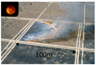 The fire ignition is controlled by two men carrying drip torches walking from the center of the upwind boundary of the plot in opposite directions. The fire ignition line starting on the windward edge of the 1ha delimited propagate then downing following an ellipsoidal shape.
The scene is simulated using the latest FDS version to date (FDS6) and provides at 25cm spatial resolution for several time steps 3D distribution of temperature, gas molar fraction for CO2, CO, H2O (xCO2, xCO, xH2O) and soot volume fraction (fv). The scene is included in DART using the DAO tool to load fluids at every voxel scene where gas molar fraction and soot volume fraction are used to compute local absorption coefficient. Soot absorption coefficient are computed as function soot volume fraction and wavelength using complex index of refraction of soot particle, see chapter 12 of Modest radiative heat transfer handbook. Following methodology used in LES-combustion model, absorption coefficient for gas mixture are pre-computed using the Statistical Narrow Band Model of EM2C (Rivier et al 2012) and a fix path length τ that is representative of the flame length of the fire. These absorption coefficient are then stored in a four-dimensional look-up-table [temperature, xCO2, xCO, xH2O] and used within the DAO tool to attribute fluid optical properties. For application to the scenario of the Case064 fire a path length of 1m is used.
Finally, to complete the DART scene, the temperature is included using a 3D temperature file created from the FDS output scene.
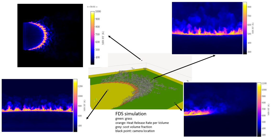
DART is then used to simulate Middle Infra Red (MIR) image of the FDS simulated fire. Camera characteristics are set to model the FLIR Agema 550.
The camera is set in DART using a pinhole model with a resolution of 320x240 pixels, a focal length of 10 mm, and a field of view of 40 degree.It is defined with a narrow spectral band located at 3.9 micron and a width of 0.02 micron. DART is then used to simulate Middle Infra Red (MIR) image of the FDS simulated fire. Camera characteristics are set to model the FLIR Agema 550.
This MIR spectral band is essential in fire monitoring as the input of this single band is enough to calculate the Fire Radiative Power (FRP) remote sensing product which can be used as a proxy for fuel mass consumption (Wooster et al 2005), see for example Paugam et al 2013 for application to airborne imagery.
DART results from the C064 fire scene simulation are shown in the image at the top of this page. While the methodology is still in the process of validation, it is interessant to see the difference in MIR brightness temperature between the camera located ahead of fire front and the other located at the back. A difference of more than 400K is showing up for the observation of the same flame. This difference is due to the presence of cool soot particles (or colder than in the flame) advected downwind of the front in the plume by the convective upddraft. This is clearly visible in the side image. The impact of this cloud of soot particleon the measurement of FRP is the subject of current research.